
MMI Stuff
MMI TR Home
Become A Ham
New Ham Help
Other Radio Services
Related Links
E-Mail Me!
Technical
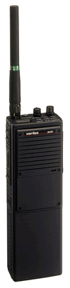
VX-5R
FT-2600M
FT-90R
FT-11R
FTH-2070
CTCSS Explained
DCS Explained
Emission Types
Technical Terms
Arizona Stuff
Emergency Repeaters
Phoenix Repeaters
ARA Repeaters
Explorer Post 599
Arizona Frequencies
Mesa Police
Mesa Fire
Phoenix Police
Phoenix Fire
Highway Patrol
Phoenix Airband
|
 General
Number of Channels: 32 Channels (VHF and UHF Shared)
Frequency Ranges:
General
Number of Channels: 32 Channels (VHF and UHF Shared)
Frequency Ranges:
150-170MHz, 450-470MHz (Prior to lot 3) Or
134-174MHz, 400-500MHz (Lot 3 and later)
Channel Steps: 5kHz (VHF) and 12.5kHz (UHF)
Power Supply Voltage: 12VDC
Current Consumption:
Standby (Saver On): 38mA
Standby (Saver Off): 60mA
Receive: 180mA
Transmit (Low): 600mA (VHF) and 700mA (UHF)
Transmit (Hi): 1200mA (VHF) and 1600mA (UHF)
Battery Life w/FNB-16 (5-5-90 duty): 8.1hrs. (VHF) and 7.0hrs. (UHF)
Operating Ambient Temperature Range: -22°F to +140°F (-30°C to +60°C)
Operating Ambient Humidity (Max.): 95% @ +50°C
Frequency Stability: ±5ppm
RF Input-Output Impedance: 50Ω
Audio Output Impedance: 8Ω
Dimensions: 7.8" x 2.6" x 1.7" (200 x 66 x 43 mm)
Weight: 29oz. (820g) w/FNB-16
Receiver
Circuit Type: Double-Conversion Superheterodyne
Intermediate Frequencies: 45MHz and 455kHz
Sensitivity: 0.25µV (VHF) and 0.35µV (UHF) For 12dB SINAD
Adjacent Channel Selectivity: 70dB
Intermodulation: 70dB (VHF) and 75dB (UHF)
Spurious and Image Rejection: 70dB
Conducted Spurious Emissions: 50dBm
Audio Response: +3/-8dB From The 6dB/Oct. De-emphasis Curve
Audio Output: 500mW Into 4Ω w/<5% THD
Hum and Noise: 45dB
Transmitter
RF Power Output: 5/1W (Both Bands)
Modulation: 16K0F3E
Maximum Deviation: ±5kHz
Conducted Spurious Emissions: >60dBc
FM Hum and Noise: 47dB
Audio Response: +1/-3dB From The 6dB/Oct. Pre-emphasis Curve
Audio Distortion: <5%
Power Amplifier Modules: M57796H (VHF) and M57797H (UHF)
Features
5 Watts Power Output
Built-In CTCSS Encoder/Decoder
Programmable VFO Steps: 5kHz (VHF) and 12.5kHz (UHF) Steps
32 Memories with 4-Character Alpha/Numeric Labels
Invertible LCD Display
TX Time-Out Timer (TOT)
TX Time-Out Resume Timer
Busy Carrier Lock-Out and Busy Tone Lock-Out
PC Programmable
Versatile Scanning Features Including Priority Scan
FCC Type Accepted for Marine Use
Aluminum Diecast Chassis
MIL-STD 810C/D/E
Accessories
FTT-5: DTMF Keypad
FDS-1: DCS/DPL Encoder/Decoder
FTE-11: Tone Burst Encoder
CD-11: Rapid Vehicular Charger
FMA-2070: Mobile Charger/Amplifier
FNB-15: 12V 600mAh, Ni-Cd Battery Pack
FNB-16: 12V 1200mAh, Ni-Cd Battery Pack
FNB-16IS: 12V 1200mAh, Ni-Cd Intrinsically Safe Battery For Use w/IS Radio
FSU-1083: Voice Inversion Encryption
FSU-460: High Security Rolling Code Encryption
F2D-4: Two-Tone Sequential Decoder (Tone Groups 1, 2, 3)
F2D-4B: Two-Tone Sequential Decoder (Tone Groups 4, 5, 6)
MH-20A12C: Speaker Microphone
NC-35: Desktop Rapid Charger
NC-36: 6-Unit Multi-Charger
LCC-2070A: Leather Case
LCS-2: Belt Swivel Attachment For LCC-2070A
VPL-1D: Radio to Computer Programming Cable w/Software
VPL-2070: Programming Adapter Cable
Serial Numbers
For all Yaesu/Vertex radios that I've seen, the serial numbers are in the format of YPXXXXXX where "Y" is the production year, "P" is the production run and "XXXXXX" is the radio's unique number.
Accessory Connector Pinout
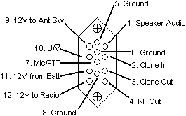 Pin 1 is the de-emphasized and amplified audio normally going to the speaker. When the accessory plug is connected, this pin will be pushed in, disconnecting the radio's internal speaker. The audio will then be routed out this connector. When the vehicular adapter is used, 12V is placed on pin 9, disconnecting the radio's antenna, via relay, and creating a path to the accessory connector (pin 4) for connection to an external antenna provided by the mobile charger/amplifier.
Disassembling Instructions
Disassembling this radio can be very confusing if you don't know exactly where to start and what to do. Here are step by step instructions on how to take this radio apart.
1. Take antenna off and take nut off connector.
2. Pull knobs off volume and channel selector.
3. On the bottom side of the radio, unscrew the two screws that are closest to the rear of the case.
4. Use a 1.5mm allen wrench to unscrew the six screws holding the front panel on.
5. Unscrew the seven screws that were behind the front panel.
6. Unscrew the two screws on top of the radio (behind the LCD, knobs, etc.).
7. Pull straight up on the top panel.
8. Gently pull the two halves of the radio apart and watch for ribbon cable and wires.
9. Disconnect the ribbon cable on rear half of the radio since it is the easiest side to put back together.
VCO Alignment
Use the graphic below for VCO alignment. To check TX VCV press PTT while measuring voltage on the "TX" test point. Use a dummy load on the antenna port during these tests.
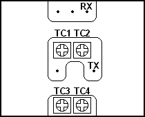
| Step |
Test Point |
Frequency |
Voltage |
Trim Cap |
| 1 |
RX |
170MHz |
4.0V |
TC2 |
| 2 |
RX |
150MHz |
1.2V |
TC2 |
| 3 |
RX |
470MHz |
4.0V |
TC1 |
| 4 |
RX |
450MHz |
2.0V |
TC1 |
| 5 |
TX |
170MHz |
3.5V |
TC4 |
| 6 |
TX |
150MHz |
2.5V |
TC4 |
| 7 |
TX |
470MHz |
3.5V |
TC3 |
| 8 |
TX |
450MHz |
2.5V |
TC3 |
CTCSS Tone Chart
You'll need this tone chart when time comes to program your radio.
| Tone |
# |
|
Tone |
# |
|
Tone |
# |
|
Tone |
# |
| 67.0 |
64 |
97.4 |
59 |
136.5 |
25 |
192.8 |
20 |
| 71.9 |
32 |
100.0 |
14 |
141.3 |
09 |
203.5 |
04 |
| 74.4 |
63 |
103.5 |
29 |
146.2 |
24 |
210.7 |
19 |
| 77.0 |
16 |
107.2 |
13 |
151.4 |
08 |
218.1 |
03 |
| 79.7 |
62 |
110.9 |
28 |
156.7 |
23 |
225.7 |
18 |
| 82.5 |
31 |
114.8 |
12 |
162.2 |
07 |
233.6 |
02 |
| 85.4 |
61 |
118.8 |
27 |
167.9 |
22 |
241.8 |
17 |
| 88.5 |
15 |
123.0 |
11 |
173.8 |
06 |
250.3 |
01 |
| 91.5 |
60 |
127.3 |
26 |
179.9 |
21 |
None |
49 |
| 94.8 |
30 |
131.8 |
10 |
186.2 |
05 |
|
|
CTCSS Squelch Tail Elimination
The FTH-2070 uses the MX-Com MX365 CTCSS Encode/Decode IC. Even though it can generate a reverse burst, it does not recognize this method of squelch tail elimination on receive. It does, however, recognize another means of squelch tail elimination on transmitters that turn the PL off a few hundred milliseconds before transmitter drop-out.
Cloning
Cloning the FTH-2070 can be accomplished by, first, enabling clone mode. This is done by holding down [PRI] while powering on the radio. "TXRX" will then flash in the display. While the radios are connected via the cloning cable (part number unknown) press [MON/R] on the RX radio and then [C/M] on the TX radio. "TX" and "RX" will be shown respectively. When the radios are done cloning "TXRX" will flash again.
Remember:
1. Connect radios with cloning cable
2. Power radios on with [PRI] depressed
3. Press [MON/R] on RX radio
4. Press [C/M] on TX radio
|
© 2003 MMI Technical Resource
|
|