
MMI Stuff
MMI TR Home
Become A Ham
New Ham Help
Other Radio Services
Related Links
E-Mail Me!
Technical
VX-5R
FT-2600M
FT-90R
FT-11R
FTH-2070
CTCSS Explained
DCS Explained
Emission Types
Technical Terms
Arizona Stuff
Emergency Repeaters
Phoenix Repeaters
ARA Repeaters
Explorer Post 599
Arizona Frequencies
Mesa Police
Mesa Fire
Phoenix Police
Phoenix Fire
Highway Patrol
Phoenix Airband
|
 General
Frequency Range:
General
Frequency Range:
TX 144-146MHz or 144-148MHz
RX 144-146MHz or 134-174MHz
Channel Steps: 5, 10, 12.5, 15, 20, 25, 50kHz
Frequency Stability: better than ±10 ppm (-20°C to +60°C)
Mode of Emission: 16K0F3E, 16K0F2D, 11K0F3E, 11K0F2D
Antenna Impedance: 50Ω unbalanced
Supply Voltage: 13.8VDC (±10%), negative ground
Current Consumption (typical):
RX: Less than 1A (max. audio), Less than 0.4A (squelched)
TX: 10A (60W), 6A (25W), 4A (10W), 3A (5W)
Operating Temperature Range: -20°C to +60°C (-14°F to +140°F)
Case Size: 160(W) x 40(H) x 160(D)mm (6.3" x 1.6" x 6.3") (w/o knobs)
Weight: 1.3kg (2.9lb.)
Receiver
Circuit Type: Double-Conversion Superheterodyne
IFs: 21.7MHz & 450kHz
Sensitivity: better than 0.2µV (for 12dB SINAD)
Selectivity: 12kHz/30kHz (-6/-60dB)
IF Rejection: better than 70dB
Image Rejection: better than 70dB
Maximum AF Output: 3.5W into 4Ω @ 10% THD
Transmitter
Output Power: 60/25/10/5W
Modulation Type: Variable Reactance
Maximum Deviation: ±5kHz/±2.5kHz
Spurious Radiation: better than -60dB
Microphone Impedance: 2kΩ
Power Amplifier Module: M67746
Features
Frequency Coverage:
RX: 134-174MHz
TX: 144-148MHz
60 Watts Power Output
Selectable TX Power: 60/25/10/5W
Direct Keypad Frequency Entry via MH-36B6J DTMF Microphone
1200/9600 bps Packet with easy interface via a dedicated rear-panel jack
175 Memories with 8-character Alpha-Numeric labels
Built-In CTCSS/DCS Encoder/Decoders
Smart Search™ Automatic Memory Loading
Omni-Glow™ multi-function LCD display
Auto-Range Transponder System (ARTS™)
Extensive MENU system
TX Time-Out Timer (TOT)
Automatic Power-Off Battery Ssaver (APO)
Automatic Repeater Shift (ARS)
S-Meter RF Squelch
ADMS-2E Windows™ PC Programmable
Supply Voltage Display
Front-mounted Speaker
TX Half-Deviation setting
Accessories
MH-36B6J: DTMF Microphone (Supplied in U.S. Model)
MH-42B6J: Condenser Microphone
SP-3: Compact External Speaker
SP-4: External Mobile Speaker w/Audio Filters
SP-7: External Loudspeaker
MLS-100: High-Power External Speaker
FP-1023A: Compact Power Supply (23A)
FP-1030A: External AC Power Supply (25A)
ADMS-2E: PC Programming Software
Download FT-2600M Manual
Serial Numbers
For all Yaesu/Vertex radios that I've seen, the serial numbers are in the format of YPXXXXXX where "Y" is the production year, "P" is the production run and "XXXXXX" is the radio's unique number.
Alignment
To access your Alignment Menu, you must build a plug that plugs into the microphone jack of the radio. Wire it so pins 1,4, and 6 are shorted together. Once in the menu, remove the special plug. Use [D/MR] and [A/N] to navigate through the menu. To make radio accept setting, hold [MHz] for one second. For S-Meter adjustments, use the RF signal generator set for 1kHz tone at �3.5kHz deviation. For Squelch adjustments, no modulation. To save the settings, short pin 6 to ground. Now your changes will be saved. Special thanks to Lorne VE1BXK for this info. It is suggested that you refer to the "FT-2600M Technical Supplement" provided by Vertex Standard. I am not responsible for any damage you may cause your radio.
| Item |
Description |
RF |
| HIP |
High Power Adjust |
60W Out |
| LO1 |
Low1 Power Adjust |
25W Out |
| LO2 |
Low2 Power Adjust |
10W Out |
| LO3 |
Low3 Power Adjust |
5W Out |
| THW |
WB Squelch Threshold |
Inject -15.0dBµ from 0.5µV |
| THN |
NB Squelch Threshold |
Inject -15.0dBµ from 0.5µV |
| TIW |
WB Squelch Tight |
Inject -3.0dBµ from 0.5µV |
| TIN |
NB Squelch Tight |
Inject -3.0dBµ from 0.5µV |
| S-1 |
S-1 Adjust |
Inject -2.0dBµ from 0.5µV |
| S-F |
S-Full Adjust |
Inject +25.0dBµ from 0.5µV |
Mic Switch Signals
The Mic Switch lines are signal outputs from the microphone to control some functions of the radio from the mic end. This is done by changing the voltage on each line to a specified value. The following table shows which function corresponds with which voltage level combination. The labels "Mic Sw1" and "Mic Sw2" are swapped between the actual mic connector and the CPU pinout. The labels listed below are according to the socket pin diagram. The levels listed below are those measured from my radio only.
| Key |
1 (Pin 1) |
2 (Pin 6) |
| None |
4.46V |
4.46V |
| PTT |
4.46V |
1.00V |
| Down |
4.46V |
2.12V |
| Up |
4.46V |
2.76V |
| ACC |
4.46V |
3.58V |
| P |
1.00V |
4.46V |
| P1 |
1.86V |
4.46V |
| P2 |
2.76V |
4.46V |
Transmit Coverage 134-174MHz Modification
This allows for transmission outside of the amateur bands. This info is intended for educational and emergency purposes only.
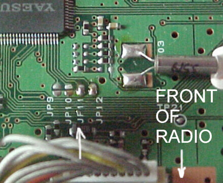 Turn the FT-2600M off and remove the DC power cable.
Remove the 5 screws securing the top cover and carefully remove it.
Locate and remove JP1011 (near Q1049) as shown above.
Reassemble the radio again.
Press and hold [A/N]+[D/MR]+[MHz] while powering up to reset the µP.
Turn the FT-2600M off and remove the DC power cable.
Remove the 5 screws securing the top cover and carefully remove it.
Locate and remove JP1011 (near Q1049) as shown above.
Reassemble the radio again.
Press and hold [A/N]+[D/MR]+[MHz] while powering up to reset the µP.
Note: When modified, this radio will not be able to clone with other unmodified radios.
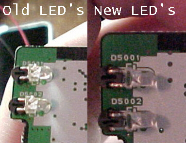
FT-2600M Display Converted To Red
Perform this mod at your own risk. I am not responsible for any damage you cause your radio. This mod may also void your warranty with Yaesu.
|
© 2003 MMI Technical Resource
|
|