| Updated 5 March 2003 | DCS Explained |
|
MMI Stuff Technical Arizona Stuff |
CDCSS
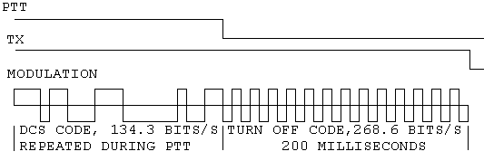
GeneralWritten by Lynn Richardson, 6 June 1995 CDCSS, also called DCS, is a digital subaudible selective signalling system. It uses a code composed of 23 bits sent repeatedly at rate of 134.3 bits per second. The code is based on the Golay (23,12) code first published in 1949. This code has the ability to detect and correct any three bit or less error that occurs in the 23 bit word. The word is composed of a 12 bit data field and an 11 bit parity vector. In CDCSS usage the 12 bits are divided into 4 octal digits, the first always being set to 100 (octal), the 2nd, 3rd and 4th digits form the three octal digit DCS code number. The word format is:
Shift Direction --> Out
Where P's are parity bits, F's are the fixed octal digit bits, and C's are the octal digit bits. For the DCS code "023" this would be the binary word:PPPPPPPPPPPFFFCCCCCCCCC  The original Golay algorithm used a binary polynomial to generate the parity bits, but this method uses too much microcontroller time and memory. Keeping all 512 23 bit words in rom would take a minimum of 1472 bytes, keeping the parity bits only in rom would take a minimum of 704 bytes. It is possible to save even more rom without taking a lot of microcontroller time by using a simpler way to calculate the needed parity bits. This method uses short calculations, one for each parity bit, based on selected bits from the 9 bit DCS code number: P1 = C1 + C2 + C3 + C4 + C5 + C8 (MODULO TWO ADDITION) P2 = NOT ( C2 + C3 + C4 + C5 + C6 + C9 ) P3 = C1 + C2 + C6 + C7 + C8 P4 = NOT ( C2 + C3 + C7 + C8 + C9 ) P5 = NOT ( C1 + C2 + C5 + C9 ) P6 = NOT ( C1 + C4 + C5 + C6 + C8 ) P7 = C1 + C3 + C4 + C6 + C7 + C8 + C9 P8 = C2 + C4 + C5 + C7 + C8 + C9 P9 = C3 + C5 + C6 + C8 + C9 P10 = NOT ( C4 + C6 + C7 + C9 ) P11 = NOT ( C1 + C2 + C3 + C4 + C7 ) DCS Transmission The DCS word is transmitted and received in NRZ (non-return to zero) format so modulation polarity is important. The definition of a "1" is an upward frequency shift and a "0" is a downward shift. DCS codes sent with this polarity are considered to be positive polarity. However some radio systems use inverted polarity to avoid interference and these are called negative DCS codes. Because of this, provision must be made to use both polarities. DCS code "+023" would be transmitted as:   The normal deviation range is from 10 to 20% of rated system deviation. Most systems are rated for 5kHz, so this would be 500 to 1000Hz CDCSS deviaton. The CDCSS modulation must be low pass filtered or have it's waveform generated in such a way that frequency products above 300Hz are reduced, otherwise they will cause an audible 'thrumming' noise on the signal. Also receivers should have a 300Hz high pass audio filter to reduce the CDCSS signal at the speaker. DCS Decoding Because there is no way to accurately determine the start of the 23 bit CDCSS code word, it is not possible to discriminate between all codes, i.e. "+023", "+340", "+766", "-047", "-375" or "-707"... all these result in the same 23 bit pattern, but shifted in time. This prevents convenient usage of all 512 possible codes. Almost all DCS codes have duplicates, so most companies use 83 to 104 of the codes, selected for low number of duplications, low falsing likelihood and good decode sensitivity. Regrettably, no industry standard recommended list of codes exists and is not likely to, so it is wise to allow for all codes and to recommend choosing from a "safe" list. A Note From Connect Systems Inc President "...we have 112 codes in our TP-163. We have 104 Codes in our TP-154. With the proper decode algorithm, it is not possible to mix up the different codes. However, each code does have an inverse." |