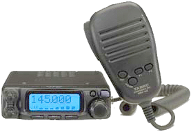
MMI Technical Resource
   Updated 2 April 2003 Yaesu Vertex FT-90R Technical   

MMI Stuff
  • MMI TR Home
  • Become A Ham
  • New Ham Help
  • Other Radio Services
  • Related Links
  • E-Mail Me!

    Technical
  • VX-5R
  • FT-2600M
  • FT-90R
  • FT-11R
  • FTH-2070
  • CTCSS Explained
  • DCS Explained
  • Emission Types
  • Technical Terms

    Arizona Stuff
  • Emergency Repeaters
  • Phoenix Repeaters
  • ARA Repeaters
  • Explorer Post 599

    Arizona Frequencies
  • Mesa Police
  • Mesa Fire
  • Phoenix Police
  • Phoenix Fire
  • Highway Patrol
  • Phoenix Airband

  • General
  • Frequency Ranges:
        RX: 100-230MHz, 300-530MHz, 810-999.975MHz (Cell blocked)
        TX: 144-146MHz or 144-148MHz (144MHz)
        430-440MHz or 430-450MHz (430MHz)
  • Channel Steps: 5/10/12.5/15/20/25/50kHz
  • Emission Type: F3, F2, F1
  • Antenna Impedance: 50Ω, Unbalanced (Antenna Duplexer built-in)
  • Frequency Stability: ±5 ppm (-5°C to +60°C)
  • Operating Temperature Range: -20°C to +60°C
  • Supply Voltage: 13.8VDC ±15%, Negative Ground
  • Current Consumption:
        300mA (Receive, Squelched)
        9.5A (TX, 144MHz)
        8.5A (TX, 430MHz)
  • Case Size: 100(W) x 30(H) x 138(D)mm (w/o knobs)
  • Weight: 640g (1.41lb.)

    Receiver
  • Circuit Type: Double-Conversion Superheterodyne
  • IFs: 45.05MHz & 455kHz
  • Sensitivity: 0.18µV @ 12dB SINAD
  • Selectivity: 12kHz/24kHz (-6dB/-60dB)
  • AF Output: 2W @ 8Ω for 10% THD
  • AF Output Impedance: 4Ω to 16Ω

    Transmitter
  • RF Power Output: 50/20/10/5W (144MHz), 35/20/10/5W (430MHz)
  • Modulation Type: Variable Reactance
  • Maximum Deviation: ±5kHz/±2.5kHz
  • Spurious Emissions: >60dB below carrier
  • Microphone Impedance: 2kΩ
  • Power Amplifier Modules: M67781L (VHF) and M57788MR (UHF)

    Features
  • 50 Watts Power Output (430MHz: 35W)
  • Ultra Compact: 100mm x 30mm x 138mm WHD (3.9" x 1.2" x 5.4")
  • AM Aircraft Receive
  • Built-In CTCSS/DCS Encoder/Decoders
  • Programmable VFO Steps: 5/10/12.5/15/20/25/50kHz per Step
  • 186 Memories with 7-Character Alpha/Numeric Labels
  • Direct Keypad Frequency Entry via MH-36A6J DTMF Microphone
  • Smart Search™ Automatic Memory Loading
  • Programmable Front Panel/Microphone Key Functions
  • Battery Voltage Meter
  • Auto-Range Transponder System (ARTS™)
  • TX Time-Out Timer (TOT)
  • Automatic Power-Off Battery Saver (APO)
  • Remote-Head Operation using Optional YSK-90 Separation Kit
  • 16-Digit 8-Memory DTMF Autodialer (requires MH-36A6J Mic)
  • ADMS-2E Windows™ PC Programmable
  • Automatic Repeater Shift
  • 1200/9600 bps Packet Compatible
  • RF-Level Squelch for Quiet Monitoring of Busy Channels
  • DCS Code # Search
  • Versatile Scanning Features
  • Priority Channel Monitoring
  • Menu for Feature Customization
  • Adjustable Display Brightness and Contrast
  • Aluminum Diecast Chassis with Cooling Fan

    Accessories
  • YSK-90: Separation Kit
  • SP-7: External Loudspeaker
  • MEK-2: Microphone Extension Kit
  • ADMS-2E: Windows™ PC Programming Software
  • MH-36A6J: DTMF Microphone (Supplied in U.S. Model)
  • MH-42A6J: Condenser Microphone

    Download FT-90R Manual

    Serial Numbers
    For all Yaesu/Vertex radios that I've seen, the serial numbers are in the format of YPXXXXXX where "Y" is the production year, "P" is the production run and "XXXXXX" is the radio's unique number.

    Slow CTCSS De-response
    The FT-90R (along with the FT-2600M) uses the MX-Com MX165C CTCSS Encode/Decode IC. The way that Yaesu incorporates it into the 90, makes the receiver mute several hundred mS late. Even though the FT-2600M uses the same chip, the de-response time on it is much more desirable. I figure that replacing the following FT-90R components with the same values that are used in the 2600M will give better performance: R2132-2.2MΩ, R2135-330kΩ, C2100-0.1uF. If anyone has a chance to test out these values in the FT-90R configuration, please let me know your results. I will try this out as soon as I have a chance.

    Squelch Problems
    The FT-90R has an infamous squelch problem that makes the receiver squelch and un-squelch at a very high rate while receiving a signal. This seems to be caused by extreme temperatures, high or low. Yaesu will do a squelch alignment for the price of $30 plus shipping. If you have access to a service monitor, you can align the squelch yourself with the aid of a $20 service manual.

    Radio Alignment
    Connect the radio to a 13.8VDC regulated power source for use on all steps. To access your Alignment Menu, you must build a plug that plugs into the microphone jack of the radio. Wire it so pins 1,4, and 6 are shorted together. Insert the plug while turning the radio on. Upon entering the Alignment Menu, take the plug out. For Receiver adjustments, use the RF signal generator set for 1kHz tone at ±3.5kHz deviation. Use the arrow buttons on the front panel to switch between each alignment item. To save levels when the RF Sig Gen is used, press the DIAL or the microphone's [VFO/MR] button. To adjust manual settings, rotate the DIAL. To change bands while in the Alignment Menu, press [SET] on the front panel. Press [DISP SS] on the front panel to save settings and exit (once alignment is complete). It is suggested that you refer to the "FT-90R Technical Supplement" provided by Vertex Standard. I am not responsible for any damage you may cause your radio.
    Item Description Adjust/Level Method
    HIPO High Power Adjust 50/35W Out Manual
    MID1 Mid1 Power Adjust 20W Out Manual
    MID2 Mid2 Power Adjust 10W Out Manual
    LOW Low Power Adjust 5W Out Manual
    MOD Modulation Adjust ±4.0kHz Deviation Manual
    SQ-S Squelch Threshold Inject -11dBµ from 0.5µV Sig Gen
    SQ-T Squelch Tight Inject -2dBµ from 0.5µV Sig Gen
    S-1 S-1 Adjust Inject -2dBµ from 0.5µV Sig Gen
    S-F S-Full Adjust Inject +25dBµ from 0.5µV Sig Gen

    Mic Switch Signals
    The Mic Switch lines are signal outputs from the microphone to control some functions of the radio from the mic end. This is done by changing the voltage on each line to a specified value. The following table shows which function corresponds with which voltage level combination. The labels listed below are according to the socket pin diagram. The levels listed below are those measured from my radio only.
    Key 2 (Pin 1) 1 (Pin 6)
    None 4.40V 4.40V
    PTT 4.40V 1.02V
    Down 4.40V 1.85V
    Up 4.40V 2.73V
    ACC 4.40V 3.53V
    VFO/MR 1.01V 4.40V
    P1 1.85V 4.40V
    P2 2.72V 4.40V

    Extended TX
    As far as I know this mod works, however, I take no responsibility for any damage you may cause your radio. It is also illegal to transmit outside of the amateur bands with this radio. This is for educational and emergency purposes only.
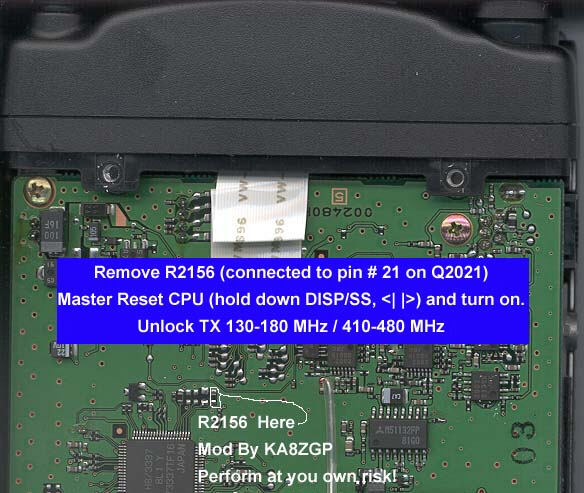
    © 2003 MMI Technical Resource