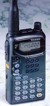
MMI Technical Resource
   Updated 2 April 2003 Yaesu Vertex FT-11R Technical   

MMI Stuff
  • MMI TR Home
  • Become A Ham
  • New Ham Help
  • Other Radio Services
  • Related Links
  • E-Mail Me!

    Technical
  • VX-5R
  • FT-2600M
  • FT-90R
  • FT-11R
  • FTH-2070
  • CTCSS Explained
  • DCS Explained
  • Emission Types
  • Technical Terms

    Arizona Stuff
  • Emergency Repeaters
  • Phoenix Repeaters
  • ARA Repeaters
  • Explorer Post 599

    Arizona Frequencies
  • Mesa Police
  • Mesa Fire
  • Phoenix Police
  • Phoenix Fire
  • Highway Patrol
  • Phoenix Airband

  • General
  • Frequency Range (MHz): 144-146 or 148
  • Channel Steps (kHz): 5, 10, 12.5, 15, 20, 25, & 50
  • Repeater Shift (kHz): ±600 (programmable)
  • Emission Type: 16K0F3E, 16K0F2D
  • Supply Voltage: 4.0-12VDC
  • Current Consumption:
        20µA Auto Power Off
        16mA Standby (Saver On)
        140mA Receive @ 11.0V w/200mW AF
        42mA Receive @ 11.0V (Unsquelched)
        1.5A Transmit (5 Watts)
  • Antenna (BNC Jack): YHA-52 Rubber Helical
  • Case Size (WHD): 57 x 123 x 26 w/FBA-14
  • Weight (approx.): 280 grams w/FBA-14

    Receiver
  • Circuit Type: Double-Conversion Superheterodyne
  • IFs: 17.7MHz & 455kHz
  • 12-dB SINAD Sensitivity: <0.158µV
  • Adjacent Channel Selectivity: >64dB
  • Intermodulation: >60dB
  • AF Output (@ 11.0V, 10% THD): 0.2W @ 8Ω

    Transmitter
  • Power Output (@ 11.0V): approx. 5.0, 3.0, 1.5 & 0.3 Watts
  • Frequency Stability: better than ±10 ppm
  • Modulation System: Variable Reactance
  • Maximum Deviation: ±5kHz
  • FM Noise (@ 1kHz): better than -40dB
  • Spurious Emissions: >60dB below carrier
  • AF Distortion (@ 1kHz): <5%, w/3.5kHz deviation
  • Microphone Type: 2kΩ condenser
  • Power Amplifier Module: S-AV28

    Features
  • 110-180MHz RX
        144-148MHz TX
  • Selectable Alpha Numeric Display
  • New Compact Battery Design
        4.8V produces 1.5 Watts
        7.2V produces 4 Watts
        9.6V produces Full 5 Watts
  • 150 Memory Channels (75 when Alpha Numeric)
  • AM "Aircraft" Receive (110-136MHz)
  • Small Compact Size w/Easy Operation (measures only: 4"H x 2.25"W x 1"D)
  • RX/TX Battery Savers
  • High-efficiency MOSFET Power Module
  • Large Back-Lit Keypad and Display
  • Up/Down Volume/Squelch Controls
  • Built-in DTMF Paging/Coded Squelch
  • Automatic Power Off (APO)

    Accessories
  • FNB-31: 4.8V, 600mAh Battery
  • FNB-33: 4.8V, 1200mAh Battery
  • FNB-35: 7.2V, 900mAh Battery
  • FNB-38: 9.6V, 600mAh Battery
  • FBA-14: 4 AA Size Battery Case
  • FTS-26: CTCSS Decode Unit
  • NC-50: Dual Slot 1-Hour Desk Charger
  • CA-10: Charge Adapter (required w/NC-50)

    Serial Numbers
    For all Yaesu/Vertex radios that I've seen, the serial numbers are in the format of YPXXXXXX where "Y" is the production year, "P" is the production run and "XXXXXX" is the radio's unique number.

    Radio Alignment
    Connect the radio to a 11VDC power source for use on all steps. DO NOT hook voltage up to the "Batt Sel" pin of the radio (this could damage the µP)! The "Batt(+)" of the radio is not used. It is suggested that you refer to the "FT-11R Technical Supplement" provided by Vertex Standard. I am not responsible for any damage you may cause your radio.


    PLL Reference Align
    Connect the wattmeter, dummy load, and frequency counter to the antenna jack. Tune the radio to 146.000MHz, key the radio and if neccessary adjust TC1001 on the Mother Unit. Make sure it is within 100Hz of 146.000MHz.

    Deviation Adjustment
    To set the deviation, set the radio to 146.000MHz and inject a 1kHz audio tone at a level of 25mV rms into the mic jack. Transmit while adjusting VR1001 on the Mother Unit for ±4.0kHz deviation maximum. Only adjust if out of ±100Hz tolerance.

    Transmitter Power Output
    Connect an inline wattmeter and 50Ω dummy load to the antenna jack. Tune the radio to 146.000MHz and set it on high power. Key the radio and adjust VR1002 on the Mother Unit for 5W power out. Confirm the following wattmeter readings on 146.000MHz and on the band edges.
    Setting Power Out
    LOW 1 0.1-0.5W
    LOW 2 1.3-2.1W
    LOW 3 2.2-3.2W
    HIGH 4.5-5.5W

    Front-end Adjustment
    Connect the RF signal generator to the antenna jack and connect the 8Ω dummy load and SINAD meter to the EAR jack. Set the radio and the signal generator to 146.000MHz. Inject the RF with a 1kHz tone at ±3.5kHz deviation. Adjust L1006, L1010, L1011 and L1018 on the Mother Unit for maximum indication on the SINAD meter. Verify at least -9dBµ for 12dB SINAD at the high and low band edges.

    Internal Alignment
    To access your Alignment Menu, set the radio to 146.000MHz, turn the radio off, and hold [VOL /\]+[VOL \/]+[CALL] while powering up. To move through alignment menu items, use the [/\] and [\/] keys. To make an alignment, hold [FM] for 1/2 second (until "Ad" is blinking in the memory box), inject the RF signal and press [MR] momentarily to save the level setting. To exit the alignment menu and save all settings, press [CALL]. Inject RF signals with a 1kHz tone at ±3.5kHz deviation.
    Item Description RF In
    S FULL S-Meter S-Full Adjust +20dBµ from 0.5µV
    S S1 S-Meter S-1 Adjust -5dBµ from 0.5µV
    SQL TH Squelch Threshold Adjust -12dBµ from 0.5µV
    SQL TI Squelch Tight Adjust -5dBµ from 0.5µV

    Transmit Coverage Modification
    This allows for transmission outside of the amateur bands. This info is intended for educational and emergency purposes only.
  • Take the radio apart.
  • Find the Control Unit under the AF Unit.
  • Open solder jumper 4.
  • Put radio back together.
  • Reset the CPU by holding [MR] + [VFO] + [2] on power up.
  • Hold [/\] + [\/] on power up.
  • Transmit coverage increased to 136-180MHz
    Note: The radio may not transmit around 136MHz and 180MHz.

    © 2003 MMI Technical Resource